Two way I2C communication between Raspberry-Pi and Arduino using logic level converter
Sep 29, 2022
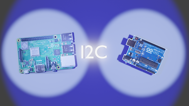
Article covers I2C communication between Raspberry-Pi 4 as controller and Arduino-Uno as target, using logic level converter.
Disclaimer
1. 2021 revision of I2C specification changed "master/slave" to "controller/target" to align with I3C bus specification for .
2. This post does not dive deeper into logic level converter. I'm planning to release another post in the future on how to test logic level converters.
3. This article does not focus on multi-controller or multi-target setup.
Working sample
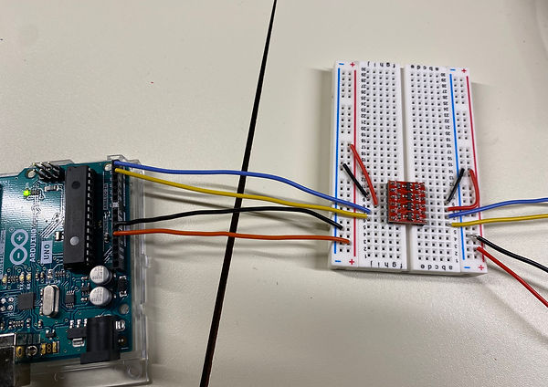
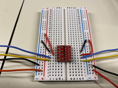
Before we proceed further, let us take a look at what our end result would look like.

Items needed
- Arduino Uno
- Raspberry Pi 4
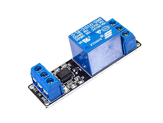
- Bidirectional logic level converter
- Breadboards and jumper wires.
Pre-requisites
This post assumes you already have,
-
Arduino Editor installed on your laptop.
-
Your laptop connected to Arduino using the USB cable.
-
Basic familiarity with Arduino programming using C++.
-
Basic familiarity with Python programming on Raspberry-Pi.
Technical details
How I2C works?
Raspberry Pi's pin's output is 3.3 V while Arduino pin's output is 5 volts.
There will be no issues if Raspberry-pi (3.3 V) sends messages to Arduino (5 V). However, if Arduino has to send message to Raspberry-Pi (5 V to 3.3 V), then we risk damaging Raspberry-Pi.
This is where logic level converter comes to our rescue.
Logic level converter has a separate 5 Volts and 3 Volts logic levels, and helps convert messages across these two levels.
Schematic & Wiring diagrams
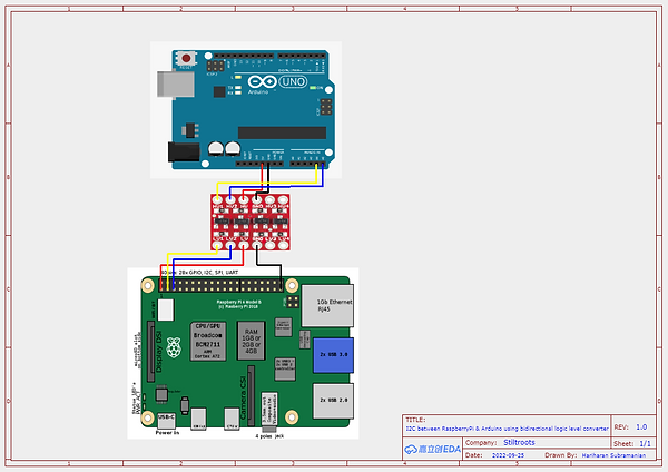
This is how the final setup looks like:
How-to steps
Step 1: Connecting Raspberry Pi (controller) to 3.3 volts side of logic level converter
Step 2: Connecting Arduino to 5 volts side of logic level controller
Step 3: Arduino C++ code
You will need SMBus library for this project.

Raspberry Pi Python & Arduino C++ code
Python Code
import time
from smbus import SMBus
addr = 0x8
bus = SMBus(1)
keepProcessing = "1"
while keepProcessing == "1":
#WORKING CODE
#dataTo_Slave = [72, 101, 108, 108, 111]
#bus.write_i2c_block_data(addr, 1, dataTo_Slave)
text = input("Message to send to slave: ")
ascii_values = []
for character in text:
ascii_values.append(ord(character))
#print(ascii_values)
bus.write_i2c_block_data(addr, 1, ascii_values)
keepProcessing = input("Continue Sending? 1-Yes & 0-No -> ")
time.sleep(1)
dataFromSlave = bus.read_i2c_block_data(addr, 0x00,30)
messageFromSlave = ""
for x in dataFromSlave:
if x > 31 and x < 123:
messageFromSlave = messageFromSlave + chr(x)
#print ("Message sent by slave as array of Ascii:", dataFromSlave)
print("Message from slave:", messageFromSlave)
Arduino C++ I2C code
There are no new libraries to be downloaded. <Wire.h> comes standard as a part of Arduino install.
#include <Wire.h>
const int ledGreenPin = 12;
const int ledRedPin = 10;
String msgFromMaster = "";
void setup() {
Wire.begin(8); // join i2c bus with address #8
Wire.onReceive(readFromMasterEvent); // register event when there is data received from master
Wire.onRequest(writeToMasterEvent); // register event when there is a request by master
Serial.begin(9600);//added by hari
pinMode(ledGreenPin, OUTPUT);
pinMode(ledRedPin, OUTPUT);
digitalWrite(ledGreenPin, LOW);
digitalWrite(ledRedPin, HIGH);
}
void loop() {
delay(5000);
}
// function that executes whenever data is requested by master. this function is registered as an event, see setup()
void writeToMasterEvent() {
String msgToSend = "Hi, did u say '" + msgFromMaster + "'?"; //WORKING CODE
Wire.write(msgToSend.c_str());
}
void readFromMasterEvent(int howMany) {
String currentMessage = "";
while (Wire.available()){
char c = Wire.read();
if(c == 0x00){
break;
}else if(c == 0x01){//Indicates a message started arriving from master
}else{
msgFromMaster = msgFromMaster + c;
currentMessage = currentMessage + c;
//Serial.print("Plain Character: "); Serial.println(c);
//Serial.print("In Binary: "); Serial.println(c,BIN);
//Serial.print("In Oct: "); Serial.println(c,OCT);
//Serial.print("In Decimal: "); Serial.println(c,DEC);
//Serial.print("In Hex: "); Serial.println(c,HEX);
//Serial.print(msgFromMaster);
//Serial.println("---");
}
}
Serial.print("Msg received from master: ");
Serial.println(msgFromMaster); delay(10000);
}
Step 5: Testing the bidirectional message communication
Now the setup should be ready to communicate between Raspberry Pi and Arduino. Please refer the last section of the video in this page to see how to test it.
Closing note
Hope this post gives you the basic details for setting up I2C communication between Raspberry-Pi and Arduino. Wishing you all the very best for your IoT projects.
Thanks,
Music by QubeSounds from Pixabay